Step 1: Gear Bracket Fit Check
The J3 GEAR BRACKET is split into two parts: upper and lower.
Use the STLOUT command to create 2 separate .stl files. Print them to check the fit against the right-angle gear box you purchased.
If the fit is good, proceed with the next steps.
If changes are needed, return to the J3 assembly.dwg file to modify these components and any other affected parts.
Step 2: Flat Bearing Press-Fit
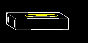
The J3 FLAT BEARING in the top portion of the J3 ARM BRACKET needs to be pressed into place.
Print this piece first to verify the hole is exactly sized for a tight press-fit.
Once you achieve the perfect fit, use those exact dimensions to create the bearing seat in the J3 ARM INNER component before printing it.
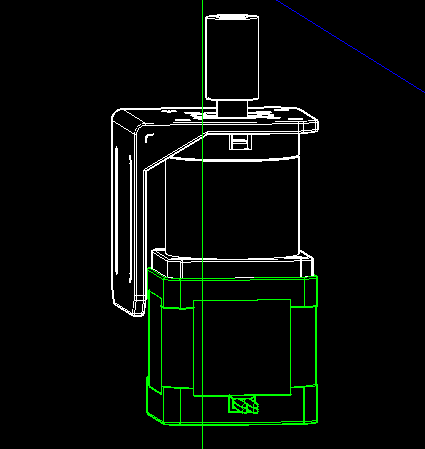
Step 3: Motor & Coupler Installation
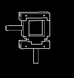
Attach the J3 MOTOR BRACKET to the J3 MOTOR using the enclosed bracket screws.
Attach the 8MM COUPLER to the J3 MOTOR shaft using the enclosed set screws.
Step 4: Gear Box and Arm Bracket Assembly
Slide the RIGHT ANGLE GEAR BOX through the 8mm FLAT BEARING in the J3 ARM INNER.
Glue all 4 pieces of the J3 ARM BRACKET together as shown below.
Glue the J3 INNER ARM to the J2 INNER ARM, and the J3 OUTER ARM to the J2 OUTER ARM.
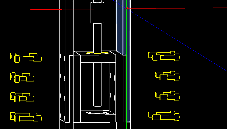
Use 8x M4 x 24 screws and M4 heat sink nuts to secure the top and bottom J3 ARM BRACKET assembly to the inner and outer J2 and J3 arms.
Use 8x M4 x 16 screws and M4 heat sink nuts to attach the J3 ARM BRACKET CENTER section to all the arms.
Step 5: Steel Rod Integration
Place the 8mm x 106mm steel rod through the 8mm flat bearing.
Attach the J3 MOTOR BRACKET, MOTOR, and 8MM COUPLER assembly to the J2 ARM INNER using 4x M4 x 16 screws and M4 lock nuts.
Tighten the set screws in the J3 8MM COUPLER onto the 8mm steel rod.
Attach the 8MM COUPLER to the RIGHT ANGLE GEAR BOX and the 8mm steel rod.
Step 6: Gear Bracket and Covers
Attach the J3 GEAR BRACKET top and bottom to the J3 INNER and OUTER ARMS using 4x M4 x 65 screws and M4 heat sink nuts.
Attach the J3 GEAR COVERS front and back using 9x M3 x 6 screws.
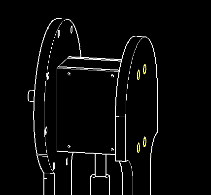
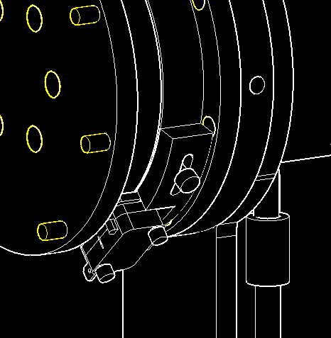
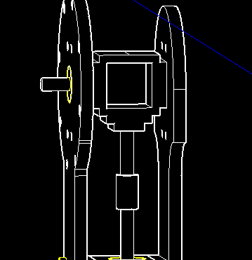
Step 7: Bearing Cup Assembly
Assemble the J3 BEARING CUP DRIVE, J3 THRUST BEARING, and J3 BEARING CUP BOTTOM.
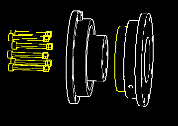
Assemble the J3 BEARING CUP ASSEMBLY and J3 FLANGE using M5 x 50 screws and M5 lock nuts.
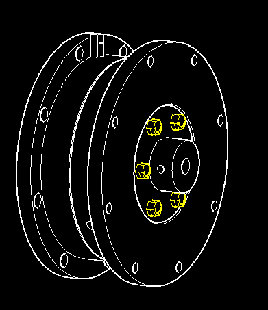
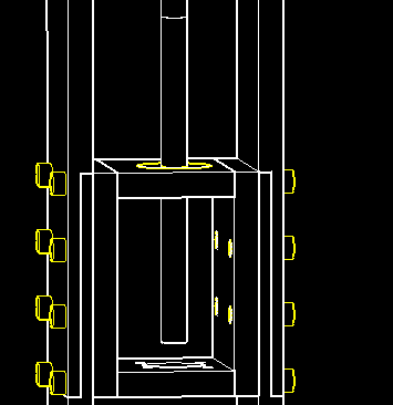
Move the J3 BEARING CUP ASSEMBLY to the J3 SPACER and tighten the J3 FLANGE set screws through the access holes in the J3 SPACER.
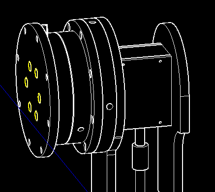
Use 8x M4 x 24 screws and M4 heat sink nuts to secure the J3 BEARING CUP BOTTOM, J3 SPACER, and J3 ARM INNER together.
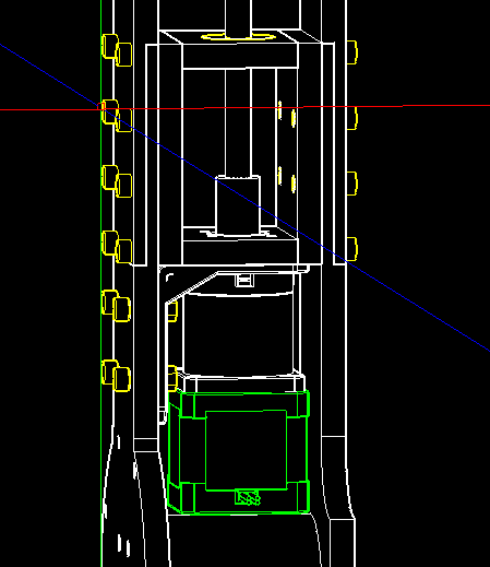
Step 8: Limit Switch Installation
Attach the J3 LIMIT SWITCH and J2 LIMIT HOLDER to the J3 BEARING CUP BOTTOM.