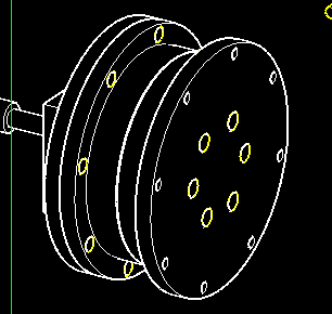
Insert J4 THRUST BEARING into J4 BEARING CUP BOTTOM.
Add J4 BEARING CUP DRIVE.
Use 6-M5 x 45 screws and M5 lock nuts through J4 BEARING CUP ASSEMBLY and J4 FLANGE.
Attach J4 MOTOR and J4 MOTOR BRACKET with screws enclosed with the bracket.
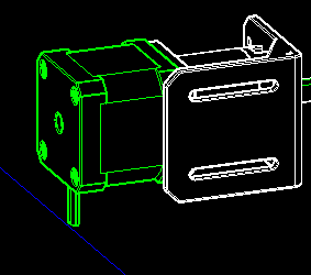
Attach 8MM x 78.5MM STEEL ROD HORZ to the shaft of J4 MOTOR with J4 COUPLER.
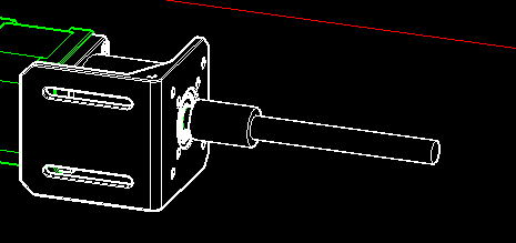
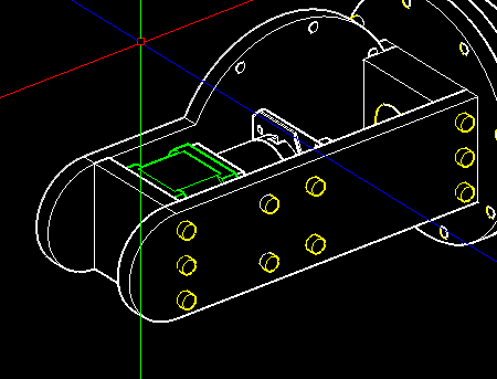
Press J4 FLAT BEARING into J4 ARM FRONT, then slide the assembly onto J4 ROD HORZ.
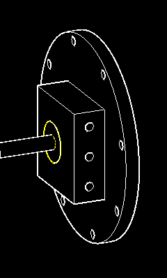
Add J4 BEARING CUP ASSEMBLY to J4 ROD HORZ and tighten J4 FLANGE with 2 enclosed setscrews.
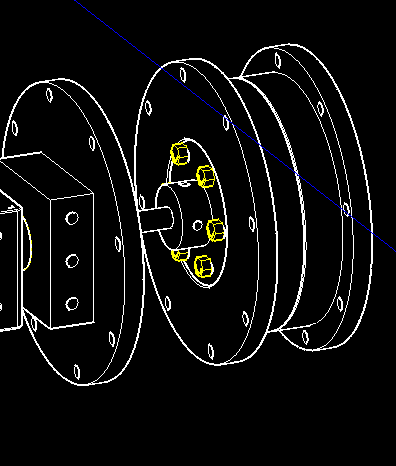
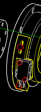
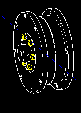
Secure J4 BEARING CUP ASSEMBLY and J4 ARM FRONT with 8-M4 x 23 screws and M4 heat sink nuts.
Attach J4 ARM OUTER, J4 ARM INNER, J4 ARM FRONT, and J4 ARM BACK with 12-M4 x 16 screws and M4 heat sink nuts. Then, attach J4 MOTOR MOUNT and J4 ARM OUTER with 4-M4 x 15 screws and M4 lock nuts.
Install J4 LIMIT SWITCH ASSEMBLY.