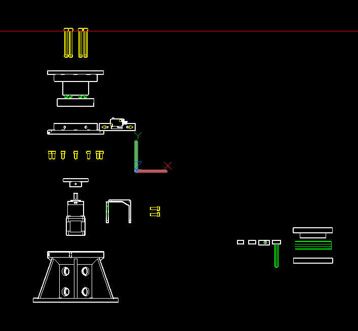
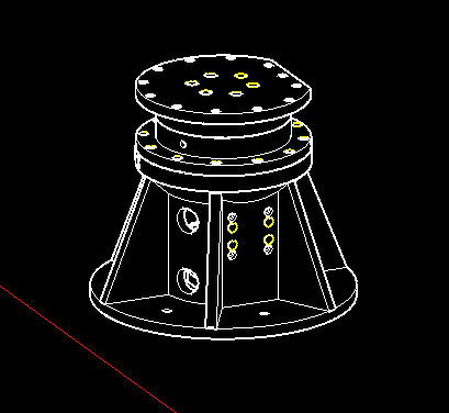
This is a J1 drawing that is broken down into various parts.
All parts need to be tested before being exported as .stl files and printed.
In the parts page of this website, I have listed the specific parts used for the J1 axis. Click on those images to visit the various suppliers and review their specifications and drawings for each part.
Different suppliers vary the sizes of every item minutely, so everything must be checked. Every 3D printer features different tolerances, so every hole (test block) in every part should be tested with your printer and adjusted if needed.
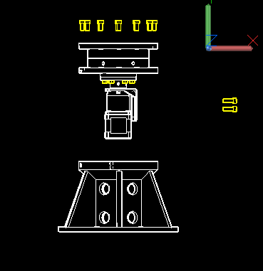
J1 Assembly Drawing
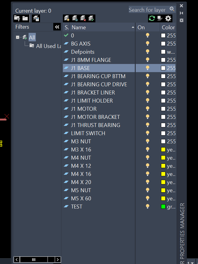
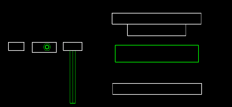
Open the layers dialog box to ensure that all layers are turned on.
You can toggle layers on and off to help recognize the specific names used for each part.
Layers Dialog Box
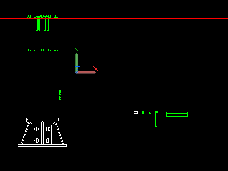
Once you are familiar with the part names, turn all layers off except “J1 BASE” and “TEST”.
You now should see the J1 base and a small piece of that J1 base on the right side of the DWG file (let’s call it the “base test”).
If you turn off the base layer, you will see the green blocks used to subtract space from the J1 base object. These holes allow the heat sink nuts to be inserted cleanly at assembly time.
They need to be perfectly sized for your specific heat sink nuts and printer setup.
Use the STL command to export the base test object on the right to a folder on your machine. Import it into your slicer and run a test print.
Insert a heat sink nut to test the overall fit. If you like the test print tolerances, you are done. If not, you will need to make adjustments to the block variations.
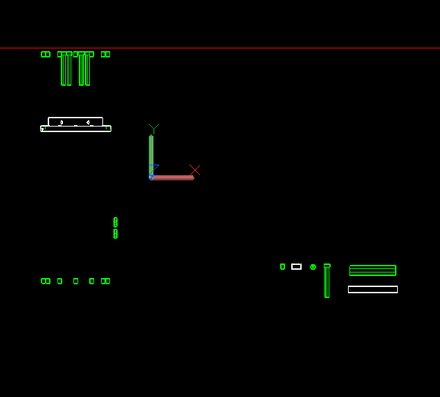
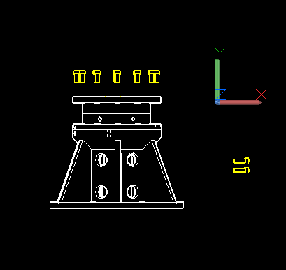
BASE and TEST Layers Enabled
Turn off the BASE layer to safely make adjustments (larger or smaller) to the green base test block.
Turn the BASE layer back on, then use the SUBTRACT or UNION commands to alter its dimensions.
Run the STL command, reprint, and retest. Repeat this cycle until it functions flawlessly.
These blocks are utilized in every single DWG file. It is vital to get them dialed in and save the final test block for future reuse.
Use the WBLOCK command to export it safely to your computer. Turn off all layers except TEST, then create a new layer using any name you prefer.
Put all the existing blocks in the base object and bearing cup drive object onto the new layer using the PROPERTIES dialog box.
COPY your finished test block to all of the original block locations. Once you have them covered, turn off the TEST layer and erase everything residing on your temporary layer.
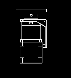
Turn the TEST layer back on. Now, follow the identical procedure for the J1 bearing cup bottom.
This particular test block is optimized for recessed or flush M4 screws. They do not strictly have to be flush on this part, so feel free to create a flush block and a non-flush block if desired. Note that flush fits are required in other DWG files.
BEARING CUP BTTM Layer Enabled
The same exact procedure applies to the J1 bracket liner. The lock nuts should fit snugly and can be secured with glue into the liner during final assembly.
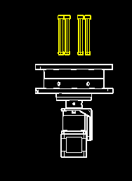
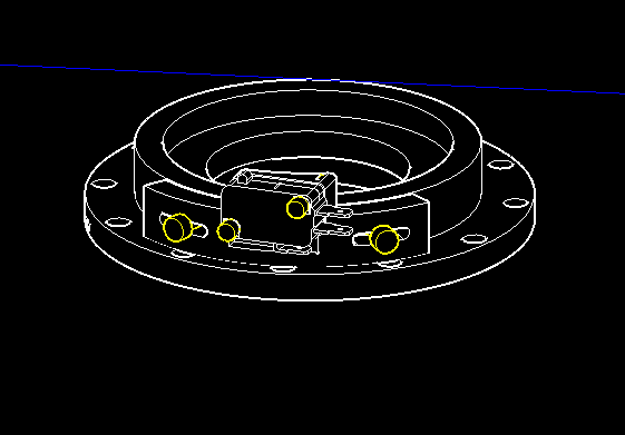
Now we are ready for the J2 bearing cup drive and bottom. This setup requires a perfect fit relative to the green test bearing.
The bearing featured in our parts list arrives in three individual pieces, all with unique dimensions. The centerpiece containing the ball bearings is smaller in diameter than the top and bottom rings. The J1 bearing cup drive must match the outside diameter as well as the inside profile of the bearing. The two distinct cups must rotate separately and freely without any structural lateral movement.
There are six total bearing cups integrated into the complete robot arm assembly.
Also, the holes for the M5 x 60 screws that attach the drive portion to the flange need to line up perfectly. The flange used in the parts list has holes that are offset in two distinct diameters, so if you purchase a different flange model, you will need to adjust the hole spacing to match your specific hardware.
The specifications for the flange used on the parts list page can be found directly on the seller's website, which is linked to the corresponding picture on our parts page.
BEARING CUP BTTM and DRIVE Layers Enabled
Assembly Instructions
Once all your check prints are complete and any necessary dimensional changes have been made to your digital files, you can go ahead and print all of the final parts.
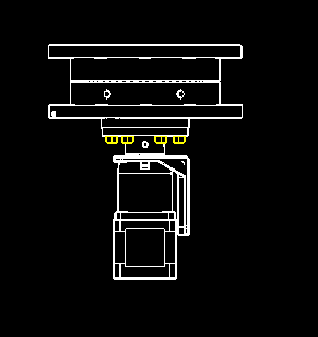
Assembly begins with the motor setup: a Nema 17 motor complete with an attached 50:1 ratio gearbox.
Add the holder liner to the motor bracket using a small amount of glue, making sure to carefully line up the screw holes.
Insert the M4 lock nuts into the liner slots and secure them in place with glue.
Mount the motor bracket to the motor gearbox using the M3 screws that were provided with the bracket hardware kit.
Attach the 8mm flange onto the gearbox output shaft and firmly tighten the set screws included with the flange.
Assemble the bearing cup drive, bearing cup bottom, and the thrust bearing together into one subgroup.
Pass the M5 screws through the bearing cup drive directly into the 8mm flange, and secure the setup tightly using the M5 lock nuts.
Slide the pre-assembled parts unit downward directly into the main J1 Base body, routing the motor wiring cleanly through one of the lower access holes molded into the base.
Install the M4 x 12 screws to firmly secure the Bearing Cup Bottom component to the main Base chassis.
Install the M4 x 20 screws to securely fasten the Motor Bracket housing onto the main Base.
Mount your Limit Switch onto the dedicated Limit Holder bracket, then attach the combined Limit Holder unit directly to the Bearing Cup Bottom.