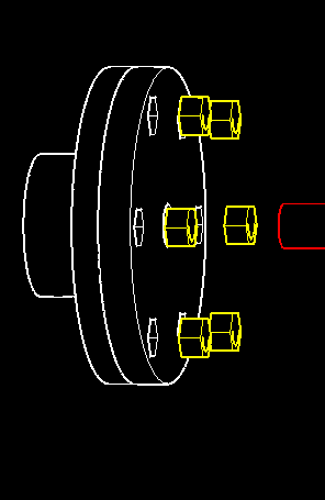
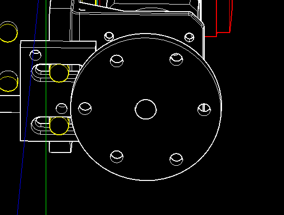
1. Press 6x M5 lock nuts into FLANGE COVER and glue FLANGE COVER to 8MM FLANGE.
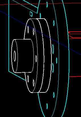
2. Slide J6 FLANGE ASSEMBLY onto J5 RIGHT ANGLE GEAR BOX SHAFT and tighten with enclosed set screws.
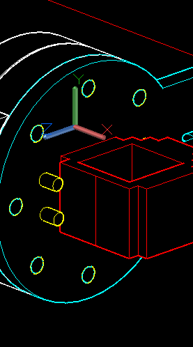
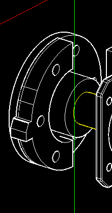
3. Assemble J6 BEARING CUP DRIVE + J6 THRUST BEARING + BEARING CUP BOTTOM.
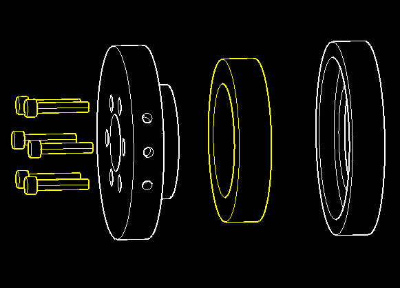
4. Attach the BEARING CUP ASSEMBLY + 8MM FLANGE with 6x M5 x 45 screws tightened to the embedded M5 lock nuts.
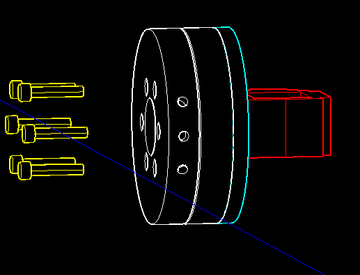
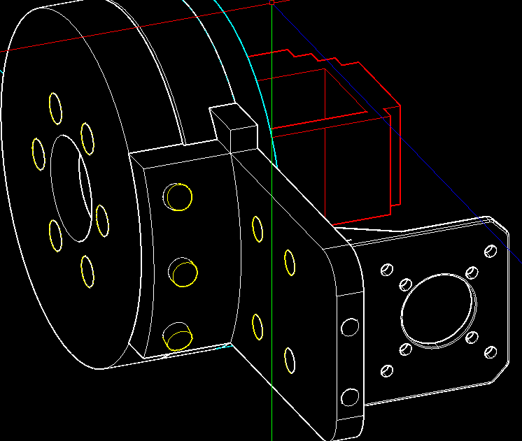
5. Attach J6 BEARING CUP ASSEMBLY + J5 ARM 1 with 8x M4 x 16 screws and M4 heat sink nuts.
6. Attach J6 ARM + J6 BEARING CUP DRIVE with 3x M4 x 16 screws and M4 heat sink nuts. Then, attach J6 MOTOR BRACKET + J6 ARM with 4x M4 x 10 screws and M4 lock nuts.
7. Attach J6 MOTOR + J6 MOTOR BRACKET with enclosed screws. Next, attach J6 COUPLER + J6 MOTOR SHAFT + 8mm x 26.3 STEEL ROD and tighten the enclosed set screws.
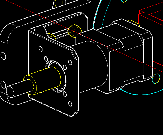
8. Attach J6 FLANGE + STEEL ROD with enclosed set screws. Then, attach J6 LIMIT HOLDER + J6 ARM with 2x M4 x 23 screws and M4 heat sink nuts.
9. Glue J6 LIMIT STRIKER + THE BACK SIDE OF J6 FLANGE, lining up the holes for future screws.
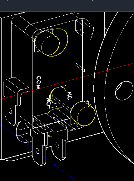
10. Attach J6 LIMIT SWITCH + J6 LIMIT HOLDER with 2x M3 x 18 screws and M3 heat sink nuts.