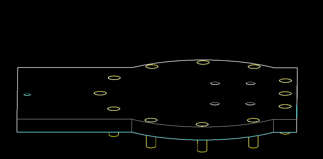
Insert 12-M4 x 12 screws into J2 PLATFORM and tighten to M4 heat sink nuts in J1 BEARING CUP DRIVE.
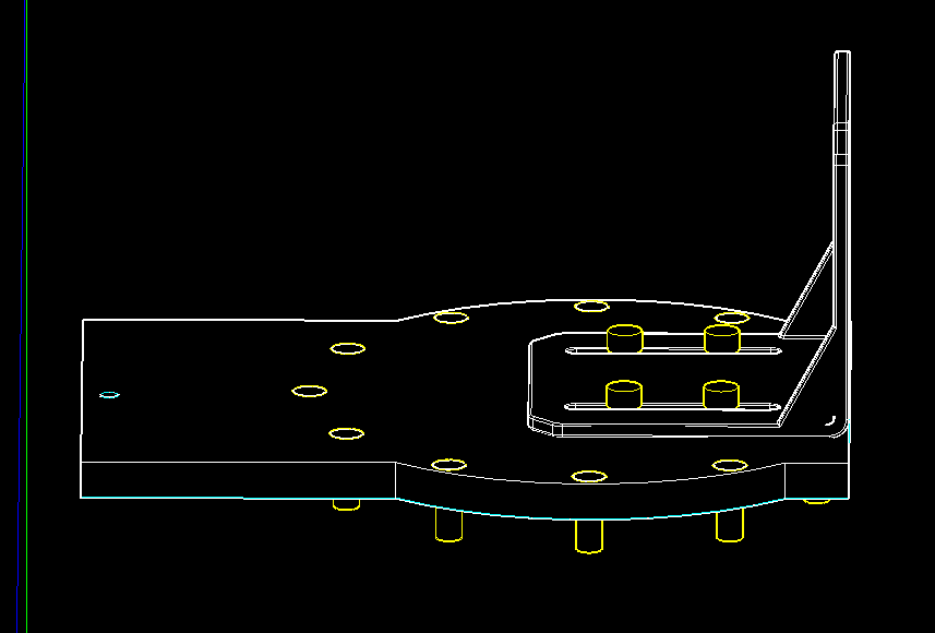
Attach J2 MOTOR BRACKET to J2 PLATFORM with M4 x 10 into M4 Heat Sink Nuts.
Place J2 Nema 23 Motor in J2 MOTOR BRACKET.
Secure J2 MOTOR and J2 SPACER to J2 MOTOR BRACKET with 4-M5 x 30 screws and M5 Lock Nuts.
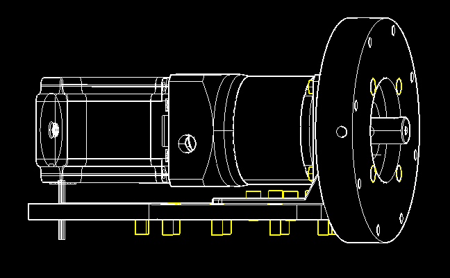
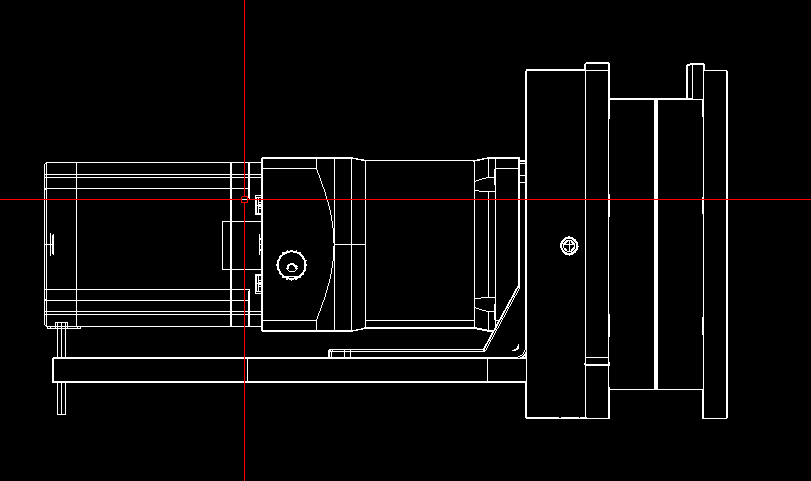
Add J2 BEARING CUP BOTTOM to J2 THRUST BEARING and J2 BEARING CUP DRIVE to J2 FLANGE.
Secure with 6-M5 x 50 screws and M5 lock nuts.
Slide the whole BEARING and FLANGE assembly onto the J2 MOTOR SHAFT.
Use a long-handled driver through the access holes in J2 SPACER to secure J2 FLANGE to the J2 MOTOR SHAFT with the set screws supplied with the flange.
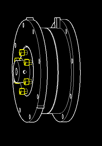
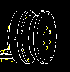
Attach J2 BEARING ASSEMBLY to J2 SPACER with 8-M4 x 12 screws and M4 heat sink nuts.
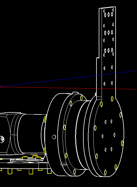
Attach J2 ARM INNER to J2 BEARING CUP DRIVE with 8-M4 x 12 screws and M4 heat sink nuts.
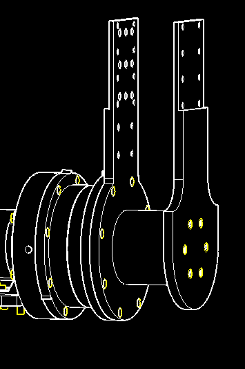
Wait untill J3 Assemblt hase been checked to print J2 ARM CENTER.
Attach J2 ARM CENTER and J2 ARM OUTER to J2 ARM INNER with 6-M4 x 65 screws and M4 heat sink nuts.