J5 Assembly Manual
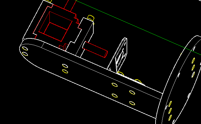
Attach the two J5 ARM 3 pieces to the J5 ARM 2 holding the J5 RIGHT ANGLE GEAR BOX with 4-M4 x 12 screws and M4 heat sink nuts.
Attach the J5 MOTOR BRACKET to the J5 ARM 2 with 4-M4 x 12 screws and M4 lock nuts.
Attach J5 ARM 2 ASSEMBLY to the J5 BASE with 3-M4 x 12 screws and M4 heat sink nuts.
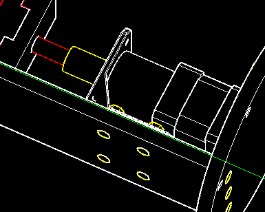
Attach J5 MOTOR + J5 BRACKET with enclosed screws.
Attach J5 COUPLER to J5 RIGHT ANGLE and J5 MOTOR SHAFT with set screws enclosed.
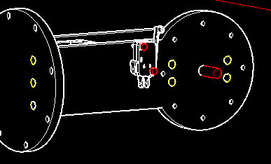
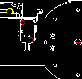
Attach J5 LIMIT SWITCH ASSEMBLY + J5 ARM 1.
Attach J5 ARM ASSEMBLY + J5 ARM 3 + J5 BASE with 7-M4 x 12 screws and M4 heat sink nuts.